Results from recent theoretical and numerical studies have emphasized the importance of the scale size of laboratory experiments. These studies show that in large systems (compared to either the ion skindepth di for low guide-field reconnection and ion sound radius ρs for strong guide fields) a transition occurs from “laminar reconnection” to “turbulent reconnection”, where the reconnection process becomes much more complicated, involving multiple reconnection sites (as illustrated in the Figure 2). The interaction between these structures can influence the total rate of reconnection in the system and may be important to particle energization.
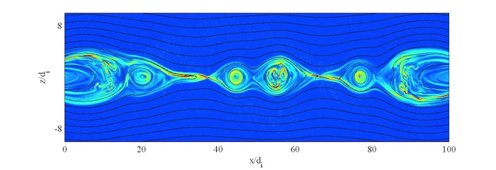
Figure 2: Structure of the total current J in a fully kinetic simulation of strong guide-field magnetic reconnection. Consistent with the phase-diagram below, multiple X-lines and flux-ropes develop in the large system size applied in this VPIC simulation (courtesy Dr. William Daughton).
As a valuable tool for displaying the various regimes of reconnection, Daughton and Roytershteyn [1] developed the reconnection phase diagram spanned by the normalized system size λ= L / di (or λ= L / Ïs) and the Lundquist number S. This diagram was also used by Ji and Daughton [2] to articulate the need for larger experiments on reconnection. In addition to the various regimes of reconnection, the diagram in Figure 3 shows the parameter space occupied by TREX as well as other experiments. The primary magnets on TREX are water cooled and can be operated in steady state for field strengths up to ~0.02T. This allows for an experimental scenario of 1Hz repetition rate between reconnection pulses such that complete datasets can be compiled with a minimal number of robotically scanned magnetic and electrostatic probes. In addition, the toroidal field magnet is designed for pulsing with fields approaching 0.3T (at R=1m), which provides access to the regime of large normalized system size L / Ïs ~1000 where turbulent reconnection is expected.
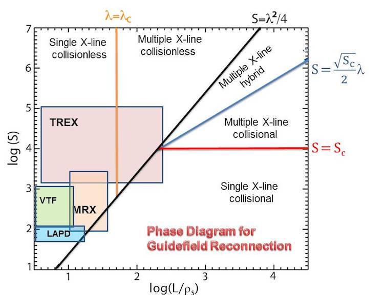
Figure 3: Reconnection phase space diagram identifying regimes of guide-field reconnection spanned by the system size normalized to Ïs and the Lundquist number S. In pulsed operation TREX will reach the regime of turbulent reconnection involving multiple X-lines
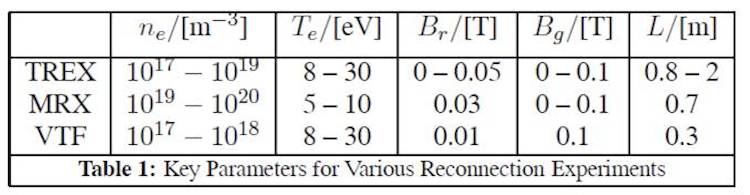
TREX is designed with large flexibility in its magnetic geometry to enable exploration of spontaneous reconnection in 3D for a range of plasma parameters, including the fully collisionless limit. Each plasma discharge will have a predetermined guide magnetic field Bg set by the currents applied in the toroidal field coils. The plasma production in TREX is aided by the novel plasma confinement scheme of MPDX. The target plasmas utilized in the MPDX dynamo experiments will be heated additionally through a scheme using induced electric fields. The table below compares important parameters of TREX with those of MRX and VTF, other magnetic reconnection devices.
[1] Daughton W and Roytershteyn V, Emerging Parameter Space Map of Magnetic Reconnection in Collisional and Kinetic Regimes, (2012) Space Science Reviews 172, 271-282.
[2] Ji H and Daughton W, Phase diagram for magnetic reconnection in heliophysical, astrophysical, and laboratory plasmas (2011) Phys. Plasmas 18, 111207.